Reading XML Reference
Read and Construct a Diagram from a XML File
This tutorial teaches you the basic step to create programmatically a diagram using the diagram library. The data for the flowchart is read from an *.xml file.
Basic Settings
We create a project in Xcode which references the diagram library using the steps from the Getting Started guide. We import the Diagramming namespace and declare a variable of type DiagramView that will be used to render the diagram:
import Diagramming
...
...
...
@IBOutlet var diagramView: DiagramView!
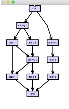
The *.xml file is just a description of a simple diagram with a few nodes and links among them:
<Graph>
    <Nodes>
        <Node id="0" name="start" />
        <Node id="1" name="activity 1" />
        <Node id="2" name="task 1" />
        <Node id="3" name="task 2" />
        ....
    </Nodes>
    <Links>
        <Link origin="0" target="1" />
        <Link origin="1" target="2" />
        <Link origin="1" target="3" />
        <Link origin="2" target="4" />
        ....
    </Links>
</Graph>
Read Data and Create Diagram Items
First we need to read and parse the data from the SampleGraph.xml file. We read the file as a string and use XmlDomBuilder object to create a hierarchical object from the string. We’ll use this data later to build nodes and connections:
//load the graph xml
let str:String? = Bundle.main.path(forResource: "SampleGraph", ofType:"xml")
let domBuilder:XmlDomBuilder = XmlDomBuilder()
domBuilder.parseFile(str!)
Now is time to create the diagram. We use the diagram property of the diagramView object we’ve already created:
let diagram = diagramView.diagram
let nodeBounds = Rect(x: 0, y: 0, width: 16, height: 8)
var map:[String:DiagramNode] = [:]
We also specify the dimensions of each node. Note the map field that we declare. It will be used to add each DiagramNode that we’ll create together with its id in a Dictionary. Let’s create a DiagramNode for each Node xml-node that was read from the file:
//load node data
let xmlElementNodes = domBuilder.root?.getChild("Nodes")?.children
for xmlNode in xmlElementNodes!
{
    let node = diagram.factory.createShapeNode(bounds: nodeBounds)
    map[xmlNode.attributes["id"]!] = node
    node.text = xmlNode.attributes["name"]!
}
We also read the id and name attributes that were retrieved from the *.xml file and assign them to the respective properties. We use the map field to add to the Dictionary DiagramNode-s, which we will pick up later when we create the diagram links. We repeat the same steps to create the diagram links from the connections data that we have parsed:
//load link data
let xmlElementLinks = domBuilder.root?.getChild("Links")?.children
for xmlLink in xmlElementLinks!
{
    diagram.factory.createDiagramLink(
        origin: map[xmlLink.attributes["origin"]!]!,
        destination: map[xmlLink.attributes["target"]!]!);
}
We use the domBuilder object to get each “Links” nodes and create a link for each one. The link is created by the Factory helper class of the diagram library. The origin and target of each link is read from the respective attributes of the Link element in the *.xml file. We use the dictionary with map fields that we’ve declared earlier to quickly pick up the right node identifying it with the id.
Layout of the Diagram
For the layout of the diagram we use one of the predefined algorithms. In this case it is the LayeredLayout.
//arrange the graph
let layout = LayeredLayout()
layout.layerDistance = 16;
diagram.arrange(layout)
diagram.labelLayoutInvalid = true
We specify the distance between layers in the layout and here is the result: